Last modified: Sun Jun 21 17:12:32 UTC+0200 2026 © A. Tarpai
The 386 is both a 32- and a 16-bit CPU at the same time. 16-bit operation and Real Mode is not a distinct operation mode. Instead, the 386 has an architecture and hardware model that can fully emulate the 16-bit 8086 operation. So already written 16-bit code could run fine together with the new 32-bit model.
8086 Emulation and the Real Mode
When the PE-bit is cleared, the CPU operates in the so called Real Mode.
The full name is Real Memory Addressing Mode, because like the 8086, memory references go right to physical memory (opposed to p-mode and virtual memory support, when the address goes through a Descriptor Table – see the P-bit in descriptors).
16-bit 8086 memory reference emulation
On the instruction-level, the default CPU operation mode, 32- or 16-bit, is determined by the currently stored Code Segment CS-ATTR D-bit (and almost has nothing to do with the PE bit). D as Default, hence the name. 32- or 16-bit operation on the instruction-level is also affected by 66/67h prefixes, see Addressing, but here lets just say the D-bit for simplicity.
16-BIT 8086 emulation is the following:
+-------+-------+    D=0
|0 0 0 0        |  <----- 16-BIT IP   JMP/CALL rel/imm/reg/mem
+-------+-------+
        |
+-------+-------+    B=0
|0 0 0 0        |  <----- 16-BIT SP   Implicit stack operations PUSH/POP/RET/INT/IRET
+-------+-------+
        |
+-------+-------+    D=0
|0 0 0 0        |  <----- 16-BIT EA   8086 addressing modes [BP/BX + SI/DI + D8/D16]
+-------+-------+
        |
        |
        v
+---------------+        +---------------+---------------+---------+
|  32-BIT OFFS  |        |  32-BIT BASE  |  32-BIT LIMIT | ATTR/AR |
+---------------+        +---------------+---------------+---------+
       |                         |
  LIMIT/ACCESS                   |
     CHECK                       |
       |           ___           |
       +----------/ + \----------+
                  \___/
                    |
                    |
              32-BIT PHYSICAL
                 ADDRESS


     386 ATTR BITS           286 AR BYTE
    <-------------> <----------------------------->
   +---+---+---+---+---+---+---+---+---+---+---+---+
   | G |D/B| 0 | V | P |  DPL  |S=1| X |C/E|R/W| A |
   +---+---+---+---+---+---+---+---+---+---+---+---+
         |
         |
The D-bit is a CS attribute (Executable segment X=1)
The B-bit is a SS attribute (X=0 and Stack segment)
16-bit EA calculation
When CS-ATTR D-bit = 0, the CPU expects legacy MODR/M bytes and 8086 addressing modes resulting in 16-bit EA values. After EA calculation EA HI is zeroed out, which clears the possible carry bit (when f. ex. BX + SI > FFFF). This emulates 64K and wrap-around. Then limit check. When limit=FFFF, 16-bit code cannot cause Exception. But limit checking is always ON. (TESTED. Set limit 0x5432, pseudo-protection fault interrupt 13 is generated. Or use 32-bit addressing mode beyond, interrupt 13).
16-bit JUMPS
When D=0, EIP HI zeroed on every JMP, Jcc, LOOP, JCXZ, CALL, RET to emulate 64K and wrap-around. See all details in JMP and CALL.
NB: this is not valid for code-execution beyond LIMIT. The 386 CPU always increments ESP for code fetch and eventually will run into limit violation – not wrap-around. An exception 13 will occur. (I tried that, bootblk code is on GitHub.)
16-bit STACK: the B-bit
When SS-ATTR B-bit = 0 for stack: change and use only the lower SP part of the 32-bit ESP for implicit stack references to emulate 64K and wrap-around (the B-bit does not apply to other data segments). Note that ESP HI stays unchanged so careful with trying to use [ESP] in 16-bit mode. Tempting – as legacy addressing modes cannot use SP as base, but make sure ESP HI is zero. See all details in PUSH.
Begs the question: why is there a separate B-bit from D-bit then?
The short reason is: the stack is a shared memory area – and the 386 was designed to completely mix legacy 8086 16-bit code with new 32-bit code.
"The B-bit specifies the size of stack pointer (the 32-bit ESP register or the 16-bit SP register) used by the processor for implicit stack references." Implicit stack references are those caused by interrupts, exceptions, and instructions such as the PUSH, POP, CALL, and RET/IRET.
The processor has to know whether SP- or ESP-addressing is the current one, when it moves data through SS-BASE+SP or SS-BASE+ESP for a PUSH/POP operation.
It could be the D-bit – but then the processor would have a problem:
- when interrupts, exceptions occur
- calls between 16/32-bit code
D=0 16-bit code
CALL/INT                   HOW TO
               --------->  PUSH?        --------->  D=? code with RET/IRET
D=1 32-bit code
CALL/INT                   SP or ESP?     may expect stack with- or without wrap-around
                                          to address parameters pushed by the processor

|___________________ B-bit a global setting above code________________________|
It cannot simply use the current D-bit: a far callee or interrupt handler might have a different D-bit setting. This could certainly mess up SP/ESP between code segments.
Eg. legacy 8086 16-bit code expects a stack area of 64K with physical address wrap-around. The B-bit makes it possible to emulate this by using only the lower SP part for the data movements. Upon return, RET/IRET should pull up the stack the same way the caller pushed – independent from 16- or 32-bit handler code.
The B-bit is something both parties have to be agreed upon and is above the D-bit setting.
Note.
For PUSH/POP the cpu performs two things:
- change and addressing by SP/ESP
- WORD/DWORD data movement
The D-bit does control PUSH/POP operations, eg. PUSH AX vs. PUSH EAX, but that is the operand-size and the 66h prefix is also honored for all these instructions.
But for the important reason above the current address-size, based on the D-bit, is ignored. 67h has no effect on PUSH/POP by the way – tried on real hardware.
8086 SEG REG emulation
When PE=0 the CPU emulates 8086-style segment base:
 WRITE SEG REG                    SEG REG DESCRIPTOR CACHE

+-----------+     PE=0      +---------------+---------+------+
|  x x x x  |   ------->    |0 0 0 x x x x 0|  LIMIT  | ATTR |
+-----------+     x 16      +---------------+---------+------+
                               32-BIT BASE
Writing SR moves value x 16 into the 32-bit BASE without affecting the rest of the DESCRIPTOR CACHE. It allows to access 1MB segmented memory. But consider:
- 386 can use 32-bit addressing modes (D-bit/67h prefix)
- no 1MB wrap-around (similar to 286) – see A20 emulation
8086 emulation on CPU RESET
Following RESET, PE = 0 and every Intel CPU behaves like a 16-bit 8086. On CPU power-up, Descriptor Cache Registers are loaded with default values:
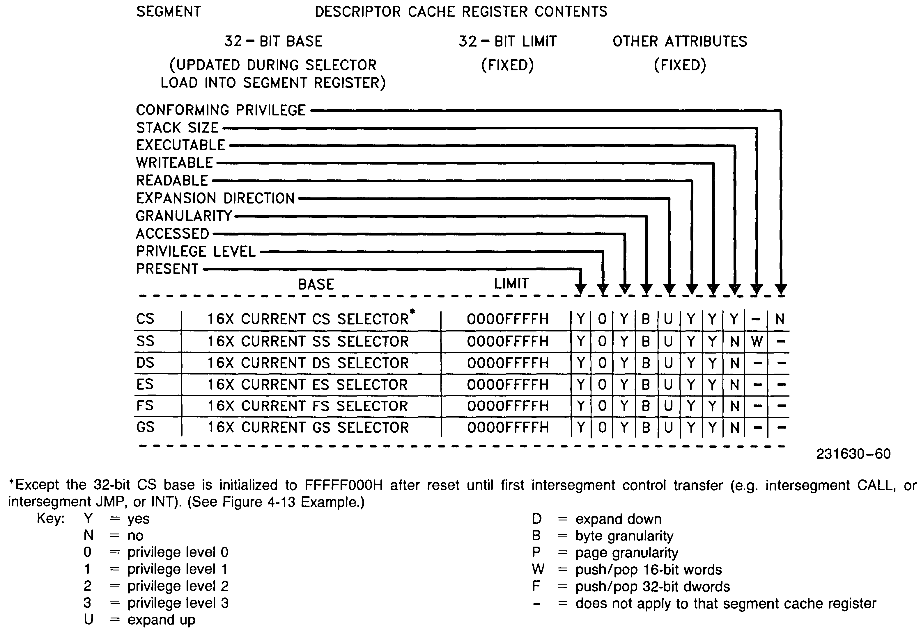
Source: 80386 HIGH PERFORMANCE 32-BIT MICROPROCESSOR WITH INTEGRATED MEMORY MANAGEMENT
April 1986 © Intel Corporation
Attribute bits, limit values are intialized in a way, so that the runnig 16-bit code (D-bit is cleared) cannot cause any violation and exception. Protection is effectively turned off (except limit-check, when memory operand crosses offset 0 or 0FFFFH and code fetch beyond limit).
IVT emulation
IVT emulation is the 8086-way vectored interrupt handling, when PE=0.
The 8086 Interrupt Vector Table (IVT) is a table of 16-bit far pointers in memory, located at address 0. When a vectored exception or interrupt occurs, the cpu fetches and loads CS:IP, the handler address, then makes the jump to handler code.
When PE=0, the 386 emulates the legacy, 8086 16-bit IVT call mechanism. No D-bit, B-bit, 66h/67h-prefix can change that (I've tried eg. 66h INT 200). The only difference is that the table can be re-located anywhere in the 4GB address space, by writing the linear address into IDTR.BASE.
      IVT structure
        in memory

  31        15        0  Vector#
  |    ..   |   ..    |  N x 4
  +---------+---------+
  |    CS       IP    |  12
  +---------+---------+
  |    CS       IP    |  8
  +---------+---------+
  |    CS       IP    |  4
  +---------+---------+
  |    CS       IP    |  0    <--- IDTR.BASE
  +---------+---------+

            |
            | FETCH
            | and
            | LOAD..
         ___|____________
        |                |
        v                v

   EIP HI zero         CS x 16
+---------------+ +---------------+---------+------+
|0 0 0 0 x x x x| |0 0 0 x x x x 0|  LIMIT  | ATTR |
+---------------+ +---------------+---------+------+
       EIP            CS-BASE
        |                 |
  LIMIT/ACCESS            |
     CHECK                |
        |       ___       |
        +------/ + \------+
               \___/
                 |
                JMP
- The received 8-bit Vector number is multiplied by 4 and added to IDTR.BASE
- IDTR.BASE is a linear address: no segmentation here
- CPU fethes 2 WORDS:
- For CS: PE = 0, so writing CS will put value x 16 into CS-BASE
- For IP: IP is zero-extended to 32-bit and written into EIP. This happens also when interrupted code D = 1! Tested.
- limit/access check (that is always on)
- Fetch instruction from EIP + CS-BASE.
NB! The IVT mechanism is meant to be used with 16-bit 8086 code: the CPU will unconditionally push 16-bit WORDS of the FLAGS, CS and IP. EIP HI is lost. Interrupt handler must be below 1MB.
IF is unconditionally cleared. Clears the TF, RF, and AC flags, in the EFLAGS register
Bootblk TEST for interrupts with PE = 0 and D = 1
Real-Address Mode Exceptions
When PE = 0 the CPU will raise some exceptions addition to 8086.
The 80386 reports some exceptions differently when executing in real-address mode (PE=0) than when executing in protected mode (PE=1): pseudo-protection faults (interrupt 12 or 13 with no error code) occur if an effective address is generated outside the range 0 through 65535." (INTEL 80386 PROGRAMMER'S REFERENCE MANUAL 1986)
An Exception is a non-maskable, internal vectored interrupt.
| 8086 | 286/386 | ||||
|---|---|---|---|---|---|
| PE=0 | PE=1 | ||||
| 0 | DIV | 0 | DIV | 0 | DIV |
| 1 | Single-step | 1 | Single Step | 1 | Single Step |
| 2 | NMI | 2 | NMI | 2 | NMI |
| 3 | INT3 | 3 | INT3 | 3 | INT3 |
| 4 | INTO | 4 | INTO | 4 | INTO |
| 5 | Intel reserved | 5 | BOUND | 5 | BOUND |
| 6 | 6 | Invalid opcode | 6 | Invalid opcode | |
| 7 | 7 | Coprocessor not available | 7 | Coprocessor not available | |
| 8 | 8 | Interrupt table limit | 8 | Double Exception | |
| 9 | 9 | Coprocessor limit (286 only) | 9 | Coprocessor limit (286 only) | |
| 10 | 10 | 10 | Invalid Task State Segment | ||
| 11 | 11 | 11 | Segment Not Present | ||
| 12 | 12 | Stack fault | 12 | Stack Segment Overrun or Not Present | |
| 13 | 13 | Pseudo-protection exception | 13 | General Protection | |
| 14 | 14 | 14 | Page fault (386 only) | ||
| 15 | 15 | 15 | |||
| 16 | 16 | Coprocessor ERROR pin | 16 | Coprocessor ERROR pin | |
| 17–31 | 17–31 | 17–31 | |||
| 32–255 | Available for INT n instruction | ||||